May 27, 2012

Auto-RP and usage of “ip pim autorp listener”

by costiser

After reading several forums with people arguing about on what routers should we use the “ip pim autorp listener” command, I have decided to write this post explaining things in my own way (of course, with a lot of pictures, as usual). Before starting, just a few words about Auto-RP:  it’s a legacy Cisco proprietary method for selecting the RP that uses two functional roles: the Candidate RPs (C-RP) and the Mapping Agent (MA).

Candidate RPs (C-RP):

    • routers willing to be RP
    • announce themselves to the MA via 224.0.1.39

Mapping Agent (MA):

    • decide who will be the RP from the Candidates RP
    • will inform the rest of the network about the elected RP via 224.0.1.40

Auto-RP uses in fact a DENSE mode fashion for distributing the announces and discoveries. For this:

  • MA must listen for 224.0.1.39
  • all multicast speaking routers must listen for 224.0.1.40


Let’s see how all works. Consider a topology with 4 routers connected in a daisy-chain fashion: R1 <–> R2 <–> R3 <–> R4.


1) configuring “ip pim sparse-mode” on all 4 routers will automatically install a (*,224.0.1.40) on all of them ( at least in IOS 12.4 – not tested in other IOSes !!! )


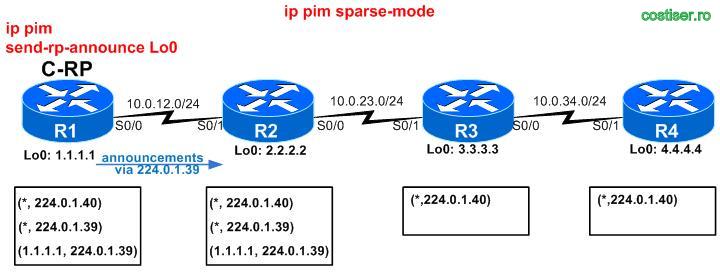
2) configure R1 to be a Candidate-RP (“ip pim send-rp-announce Lo 0“)

=> R1 announce itself as candidate RP via 224.0.1.39 in a DENSE-mode fashion (to all its neighbors):

!! R2 will not forward these announcements !!

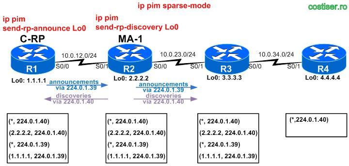
3)  configure R2 to be a Mapping Agent (“ip pim send-rp-discovery Lo 0“)

=> R2 selects the RP from all the candidates (in our case only R1)
=> R2 informs everybody about the selected RP via 224.0.1.40 in a DENSE-mode fashion
=> R2 also forwards the announcements that it received from R1 (via 224.0.1.39) !! – this is because there may be redundant MAs in the network
 
 !! R3 will not forward these announcements !! 

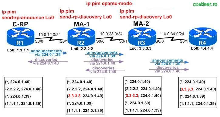
4)  configure R3 to be a redundant Mapping Agent (“ip pim send-rp-discovery Lo 0“)

=> R3 receives the announcements sent by R1 (because it happens to be neighbor with the MA-1, R2, that forwards them)
=> R3 selects R1 as RP
=> R3 informs everybody about the selected RP via 224.0.1.40 in a DENSE-mode fashion
=> same as R2, also R3 forwards the announcements that it received from R1 (via 224.0.1.39) !!
At this moment, all 4 routers know the RP via Auto-RP with the following note:
  • R1 sees the source of info as being 2.2.2.2 (R2 = MA)
  • R2 sees the source of info as being 1.1.1.1 (R1 = C-RP)
  • R3 sees the source of info as being 1.1.1.1 (R1 = C-RP)
  • R4 sees the source of info as being 3.3.3.3 (R3 = redundant MA)

Another important note:  I did not use the “ip pim autorp listener” on any of them !!!  I only took advantage of the fact that this command is needed only on routers that are in transit of those groups (routers that need to forward the DENSE information for 224.0.1.39 & 224.0.1.40).

If a 5th router had been connected to R4, then in order for R5 to receive the Auto-RP messages we would have needed to configure “ip pim autorp listener” on R4.
Conclusion:  ip pim autorp listener” is not needed on routers that are adjacent to the MA !
June 27, 2011

ACLs Supported on 3560 & 3750 Switches – Part II (VLAN Maps)

by costiser

This is the second part of a long post about ACL types that are supported on 3560 & 3750 series switches. If you missed the first part, take a look here:

ACLs Supported on 3560 & 3750 Switches – Part I (Port ACL and Router ACL)
 

In this post we will discuss about the VLAN ACLs also known as VACL or VLAN Maps.

June 26, 2011

ACLs Supported on 3560 & 3750 Switches – Part I (Port ACL & Router ACL)

by costiser

After a nice vacation, here I come again with a new post, this time about several ACL types that are supported on 3560 and 3750 series switches.

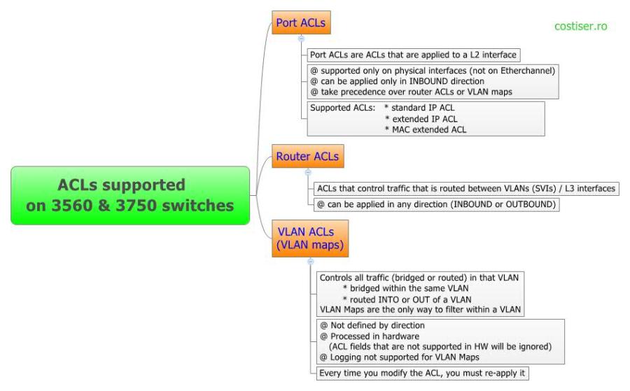
As you can see in the above chart, there are 3 types of ACLs supported on these switches:

  • Port ACLs
  • Router ACLs
  • VLAN ACLs (VLAN Maps)

Let’s take them one by one.


1.Port ACLs

Port ACLs are ACLs that are applied to Layer 2 interfaces on a switch.
Port ACLs are supported only on physical interfaces (not on EtherChannel interfaces) and can be applied only in the inbound direction.
For example, if you apply a port ACL to a trunk port, the ACL filters traffic on all VLANs present on the trunk port.
If you apply a port ACL to a port with voice VLAN, the ACL filters traffic on both data and voice VLANs.

YOu should have in mind that there are more access-lists that can be used as Port ACL. Here is how you can use them:

Numbered Standard IP ACL (ACL numbers 1-99, 1300-1999)

(config)# access-list 5 deny host 192.168.1.1
(config)# access-list 5 permit any

Numbered Extended IP ACL (ACL numbers 100-199, 2000-2699)

(config)# access-list 105 deny tcp 192.168.1.0 0.0.0.255 172.16.1.0 0.0.0.255 eq telnet
(config)# access-list 105 deny udp 192.168.1.0 0.0.0.255 172.16.1.0 0.0.0.255
(config)# access-list 105 permit ip any any

Named Standard and Extended ACLs

(config)# ip access-list standard Stnd_ACL
(config-ext-nacl)# permit 192.168.1.1
(config)# ip access-list extended Extd_ACL
(config-ext-nacl)# deny tcp 192.168.1.0 0.0.0.255 172.16.1.0 0.0.0.255 eq telnet
(config-ext-nacl)# deny udp 192.168.1.0 0.0.0.255 172.16.1.0 0.0.0.255
(config-ext-nacl)# permit ip any any

Named MAC Extended ACLs
You can filter non-IPv4 traffic on a VLAN (VLAN Maps) or on a Layer 2 interface (Port ACL) by using MAC addresses and named MAC extended ACLs.
The procedure is similar to that of configuring other extended named ACLs.
– You cannot apply named MAC extended ACLs to Layer 3 interfaces.
– You cannot use mac access-group command on EtherChannel ports

(config)# mac access-list extended ACL_MAC
(config-ext-macl)# permit any host 00c0.00a0.03fa netbios
(config-ext-macl)# deny any any 0x4321 0

(config)# interface gigabitethernet1/0/2
(config-if)# mac access-group ACL_MAC in

2. Router ACLs

There are not so many things to be said about the Router ACLs. Take a look to the above section and you’ll see how to create standard and extended, numbered and named ACLs.

The important differences that you need to remember are: Router ACLs control traffic that is routed between VLANs (SVIs) or L3 interfaces and they may be applied in both direction (inbound and outbound).


The last section, VLAN ACLs, will be discussed in next post:

ACLs Supported on 3560 & 3750 Switches – Part II (VLAN Maps)

May 27, 2011

OSPF on CE-PE links

by costiser

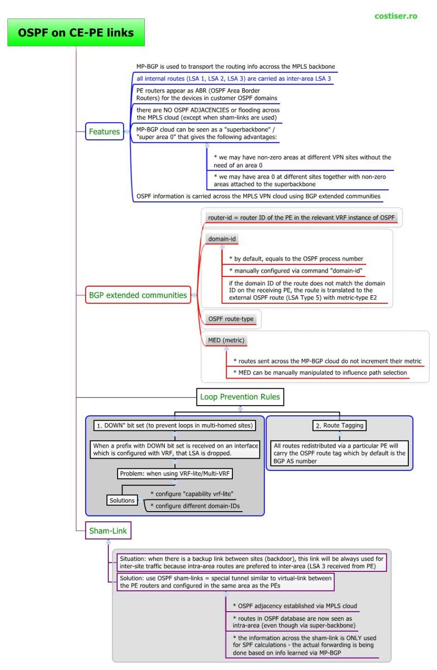
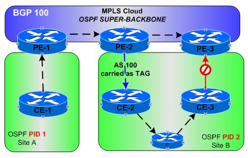
And here it comes a prettly long post. For those without too much free time (I also include myself here), you can take a fast look at the drawing above. If you liked it and want to find out more details, then go ahead and read this till the end (other cool drawings will come as well below:-) ).

Let’s start with some basic comments/features:

  • MP-BGP is used to transport the routing info accross the MPLS backbone
  • all internal routes (LSA 1, LSA 2, LSA 3) are carried as inter-area summary Type-3 LSAs
  • PE routers appear as ABR (OSPF Area Border Routers) for the devices in customer OSPF domains
  • there are NO OSPF ADJACENCIES or flooding across the MPLS cloud (except when sham-links are used)
  • MP-BGP cloud can be seen as a “superbackbone” / “super area 0” that gives the following advantages:
    •     we may have non-zero areas at different VPN sites without the need of an area 0
    •     we may have area 0 at different sites together with non-zero areas attached to the superbackbone
  • OSPF information is carried across the MPLS VPN cloud using BGP extended communities

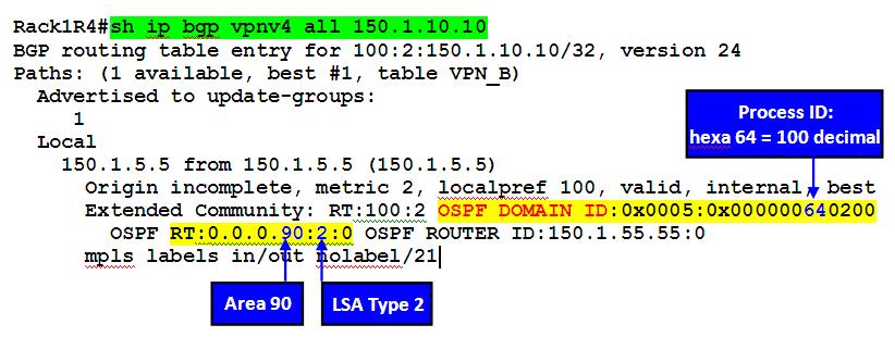
The BGP extended communities used to carry OSPF information are:

  • router-id = router ID of the PE in the relevant VRF instance of OSPF
  • domain-id
    • by default, equal to the OSPF process number
    • manually configured via command “domain-id”
    • if the domain ID of the route does not match the domain ID on the receiving PE the route is translated to the external OSPF route (LSA Type 5) with metric-type E2
  • OSPF route-type
  • MED (metric)
    •   routes sent across the MP-BGP cloud do not increment their metric
    •   MED can be manually manipulated to influence path selection

Loop Prevention Mechanisms

The addition of the super-backbone area also introduces the possibility of routing loops. In order to prevent them, several basic loop prevention rules apply:

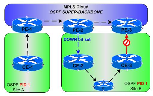
1) “DOWN” bit set (to prevent loops in multi-homed sites)
= Automatically set in all summary LSA 3 (not in LSA 5)  when routes are redistributed from MP-BGP into OSPF.
When a prefix with DOWN bit set is received on an interface which is configured with VRF, that LSA is dropped.
(correct sentence is: that LSA is not considered during the SPF calculations)

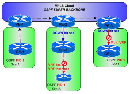
This feature has undesirable effect when using VRF-lite in the customer cloud:

The solutions to this problem:
A) is to configure the command “capability vrf-lite” on the customer router(s), but this is not supported on all IOS:

router ospf 1 vrf VPN_A
capability vrf-lite

B) configure different domain-IDs as this will force all redistributed routes to become external (LSA 5, thus bypassing the DN bit check)

*  *  *

2) Route Tagging
The DN bit helps preventing routing loops when summary Type-3 LSAs are redistributed, but not when external routes are announced (the DN bit is not set on LSA Type 5/7)
= All routes redistributed via a particular PE will carry the OSPF route tag which by default is the BGP AS number.
This tag is preserved when the external route is propagated across the entire OSPF domain (including redistribution into another OSPF domains). When another PE receives this route and it sees that the local AS number matches the AS number in the tag, it will ignore this LSA.

router ospf 1 vrf VPN_A
 domain-tag 777

or

router ospf 1 vrf VPN_A
 redistribute bgp 100 subnets tag 777

Sham-Link

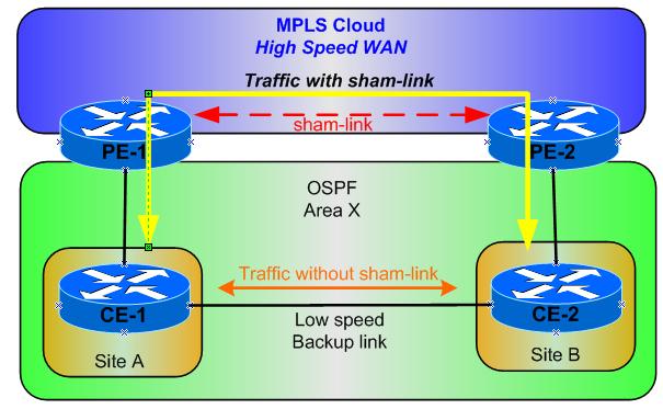
Situation/problem description: when there is a backup link between sites (backdoor), this link will be always used for inter-site traffic because intra-area routes (LSAs received via backdoor) are preferred to the inter-area (LSA 3 received from PE).
The solution to this problem is the usage of OSPF sham-links = special tunnel similar to virtual-links between PE routers and configured in the same area as the PEs.

Sham-links have the following characteristics:

  • OSPF adjacency established via MPLS cloud
  • routes in the OSPF database are now seen as intra-area (even though they are received via the super-backbone)
  • the information across the sham-link is ONLY used for SPF calculations – the actual forwarding is being done based on the info learned via MP-BGP

One last note about sham-links: sham endpoints IP addresses should be advertised into the VRF by means other than OSPF (commonly via BGP) – known before creating the sham-links.

I hope you did not fell asleep reading this long post. At least the drawings helped you do a faster “reading”.

May 23, 2011

Subtle difference for PORTFAST & BPDUFILTER used together globally or at interface-level

by costiser

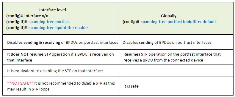
Portfast + bpdufilter (used together) can be enabled globally or at interface level:

Globally:

(config)#  spanning-tree portfast bpdufilter default

At interface level:

(config)#  interface x/x
(config-if)#  spanning-tree portfast
(config-if)#  spanning-tree bpdufilter enable

Although the first impression is that the only difference is the global or per-interface effect, this is not entirely true and another subtle and important difference is described below.

By default, a port configured with portfast is still sending out BPDUs. If you want portfast-enabled ports to stop sending BPDUs you may rush to use command (config-if)# spanning-tree bpdufilter enable on the same interface.
While this gives you what you want (don’t send BPDUs on portfast interfaces), you have the following problem: you disable completely STP on that port, meaning that you stop both sending and receiving BPDUs. This is NOT SAFE as it may result in STP loops (in case you connect a BPDU-enabled device on that port).

A better option (and here it comes up the subtle difference that I talked about) is to enable bpdufilter globally for all portfast-enabled ports: (config)# spanning-tree portfast bpdufilter default.
This command stops, as well, sending BPDUs on the portfast interfaces, but in case a BPDU is received on that port, it will resume STP operations on it, thus preventing STP loops. If a BPDU is received, that port loses its portfast status immediatelly and starts following the STP rules/states.

May 16, 2011

Matching packets based on their size

by costiser

Welcome on my very first post on my new fresh technical blog!  This post shows different ways of how to match packets based on their length. While this may not be very common in real production, you will find it for sure during your CCIE lab exam.

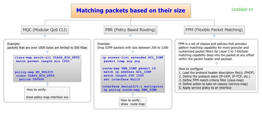
There are 3 ways (at least, those that I am aware of) to match packets by their size:

1. MQC  (Modular QoS CLI)

In the following example, we are given the task to limit to 500 Kbps all the packets that are over 1000 bytes in size. Using the MQC, you create a class-map matching the length of the packet, then create a policy-map to apply the police action to this class and finally apply it to on interface:

class-map match-all CLASS_BIG_PKTS
 match packet length min 1300

policy-map MY_POLICY
 class CLASS_BIG_PKTS
    police 500000

After applying the service-policy to an interface, you may tested by ICMP with packets of different sizes. To verify it, use the following command:

Router-1#sh policy-map inter fa0/0
 FastEthernet0/0

  Service-policy output: MY_POLICY

    Class-map: CLASS_BIG_PKTS (match-all)
      10 packets, 10150 bytes
      5 minute offered rate 2000 bps, drop rate 0 bps
      Match: packet length min 1000
      police:
          cir 500000 bps, bc 15625 bytes
        conformed 10 packets, 10150 bytes; actions: transmit
        exceeded 0 packets, 0 bytes; actions:
          drop
        conformed 2000 bps, exceed 0 bps

    Class-map: class-default (match-any)
      26 packets, 2310 bytes
      5 minute offered rate 0 bps, drop rate 0 bps
      Match: any

2) PBR (Policy Based Routing)

Using route-maps gives you also the possibility to match packets by their sizes. In the below example, all ICMP packets with size between 200 and 1200 will be dropped:

ip access-list extended ACL_ICMP
 permit icmp any any

route-map PBR_ICMP permit 10
 match ip address ACL_ICMP
 match length 200 1200
 set interface Null0

interface Serial0/0.1 multipoint
 ip policy route-map PBR_ICMP

To verify it, initiate pings with diferrent sizes and then check the route-map on the router:

Router-1#sh route-map
route-map PBR_ICMP, permit, sequence 10
  Match clauses:
    ip address (access-lists): ACL_ICMP
    interface FastEthernet0/0
    length 200 1200
  Set clauses:
    interface Null0
  Policy routing matches: 10 packets, 1290 bytes

3) FPM (Flexible Packet Matching)

I don’t believe that FPM may appear during CCIE R&S lab exam. It is more probable to see it during the CCIE Security exam. Anyway, here’s a quick referrence about it:

FPM is a set of classes and policies that provides pattern matching capability for more granular and customized packet filters for Layer 2 to 7-bit/byte matching capability deep into the packet at any offset within the packet header and payload.

How to configure
Step 1. Load the protocol header description file(s) (PHDF)
Step 2. Define the protocol stack (IP-UDP, IP-TCP, etc.)
Step 3. Define FPM match criteria filter (class-map)
Step 4. Define action to take on classes (service-map)
Step 5. Apply service policy to an interface

Cisco doc: http://www.cisco.com/en/US/prod/collateral/iosswrel/ps6537/ps6586/ps6723/prod_white_paper0900aecd80633b0a.html